Curious? I was too.
I owe you at least a few words about the components that went into this madness. If you’ve made it this far, you deserve some details!
I’ve highlighted and numbered important parts on the PCB, and below, you’ll find an explanation of each of them. The Essential PCB is basically the same—just without the USB hub circuits.
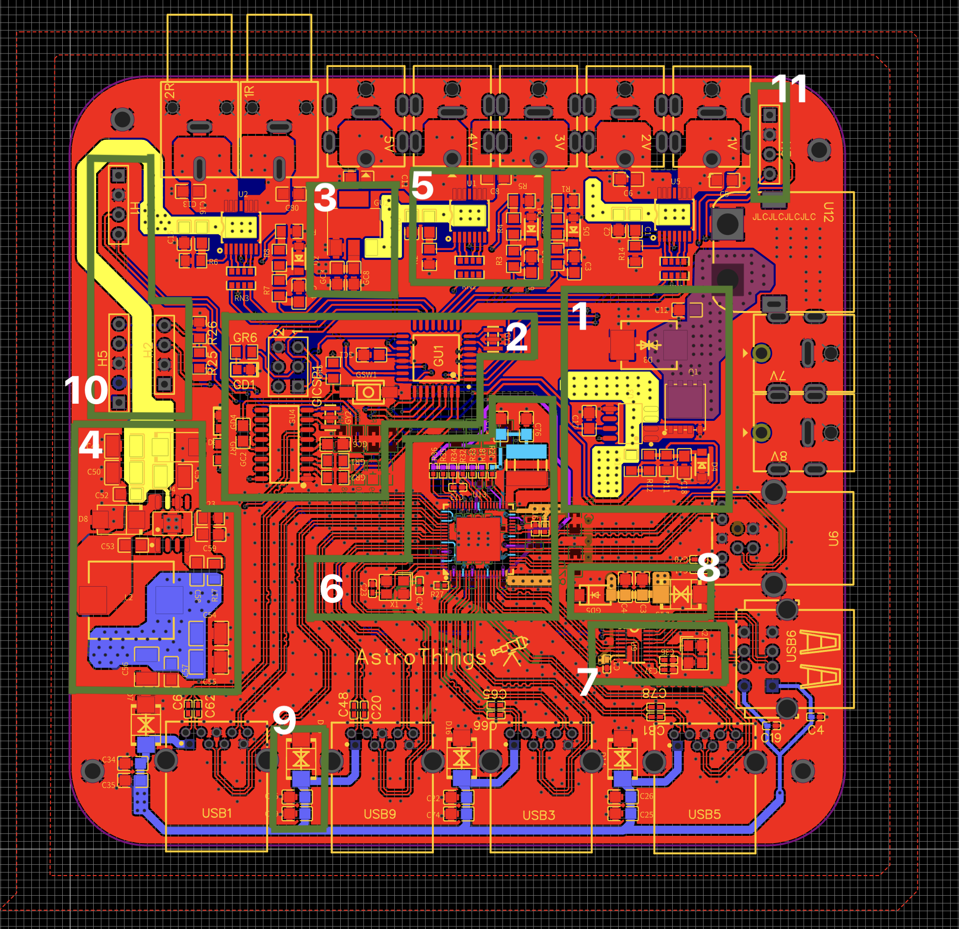
1. Power Input & Protection
- The main power enters through an XT60 connector (rated for 60A—overkill, but hey, why not?).
- The SMCJ33CA/TR13 TVS diode protects the circuit from voltage spikes.
- A P-channel MOSFET prevents reverse voltage from frying the board.
- A current sensor logs power usage and provides software-based protection against over/undervoltage.
2. Microcontroller Circuit
- The brain: ATMEGA328-AU.
- USB-to-serial communication: CH340C chip.
- Hard reset button and a 6-pin header for direct programming.
3. Basic 12V to 5V Voltage Regulator
- Powers low-consumption components like the microcontroller and switches.
4. High-Power Step-Down Circuit (12V to 5V)
- Powers USB outputs and other high-consumption components.
- Uses the TPS5450DDAR step-down regulator (5A, 20V input) from Texas Instruments.
- Features a 15µH, 5A inductor for efficiency.
5. Intelligent Output Control
- Manages high-side switching for various loads.
- Uses Infineon BTS70082EPA, supporting up to 8.2A per channel.
- Provides overcurrent, over-temperature, and short-circuit protection.
- Includes current sense feedback for monitoring.
- Both Pro and Essential versions have 3 of these circuits, allowing up to 6 controlled outputs.
6. USB 3.0 Hub
- Powered by the VIA Labs VL813 chip, supporting up to 4 USB 3.0 ports.
7. USB 2.0 Hub
- Uses the SL2.1s chip, also supporting 4 outputs.
- One USB 3.0 hub data line is dedicated to this USB 2.0 hub.
- Connected devices:
- Two USB 2.0 outputs
- Microcontroller
- One unused port
8. Power Routing & Backup Supply
- Passes 5V from USB input to the hub and keeps low-power components running if 12V is unavailable.
9. USB Protection Circuit
- Protects against ESD (Electrostatic Discharge), voltage spikes, and transients.
- Uses a TVS diode on each USB hub output for stability and compliance.
10. Expansion Headers
- Right 4-pin header: Connects a Bluetooth module for wireless control.
- Top 4-pin header: I2C output for external sensors.
- Left 5-pin header: Provides a 12V/5V power output and control lines for advanced external modules.
11. Temperature & Humidity Sensor Slot
- Leave this empty during SMT assembly.
- Attach an AHT10 sensor manually (you can get it here).
Building Your Own PowerBox: The Files & The Process
All Gerber, Pick & Place, and BOM files are available on my GitHub repository.
Ordering the PCB
- Choose your manufacturer: JLCPCB or PCBWay.
- Upload the Gerber file.
- Select either:
- PCB only (You will solder everything yourself)
- PCB + SMT assembly (Let someone else to do it)
- For SMT service:
- Triple-check out-of-stock or substitute components.
- Avoid “special parts” if possible—opt for “Basic” parts to cut costs.
- Even if my BOM shows “special parts”, there might other parts that fits - they are changing it all the time.
Sourcing the USB3 Chip (Pro Version Only)
- VL813 is usually NOT in stock at PCB manufacturers.
- Order from AliExpress or Alibaba.
- Soldering this thing is very tricky - you three options:
- DIY (Warning: This is hard!)
- Consign the chip to your PCB factory (both JLCPCB & PCBWay allow this, and sometimes they also do wrong…).
- Preffered - Go to a lab near you house, and pay them to solder it - this is the best way to ensure it is soldered correctly.
Best way to check if it’s working is…well…connecting it to your computer and see if you get a new “Generic SuperSpeed USB Hub” in your device manager, as well as a COM port which is the microcontroller indicating that the USB2.0 hub is working as well. Tips for the lab technician:
- The top side of the resistors R32-36 located above the USB3 chip should measure 3.3v while the USB cable is connected.
- The most right resistors one on the same line R20 should measure 1.2v.
If one of the requirments above are not met this is 95% chance for bad soldering of the USB3 chip and 5% chance for bad chip. In addition, you can check that the bottom side of the R16 resistor located on the right of the chip measures 3.3v
If (and only if) the USB3 and USB2 outputs are working, but your computer cannot identify the COM port of the microcontroller, try installing the CH340 drivers (Google it).
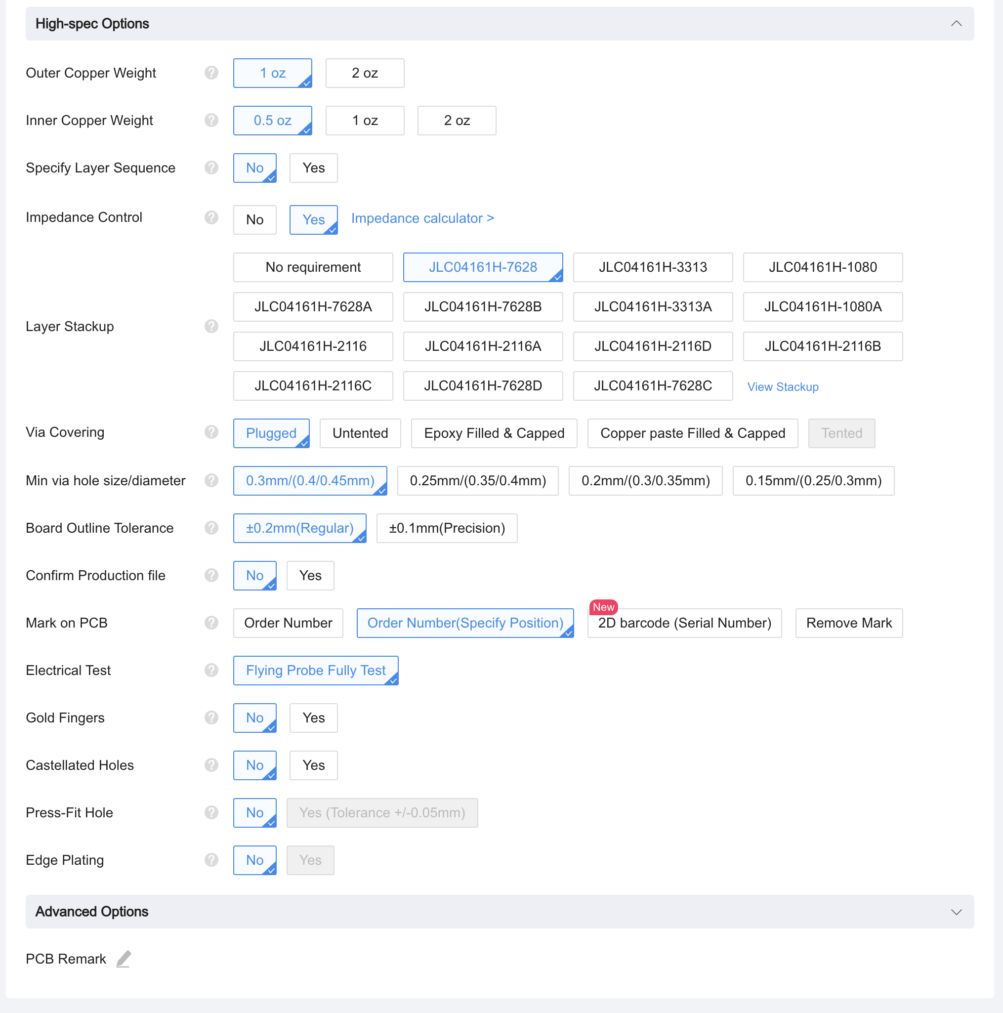
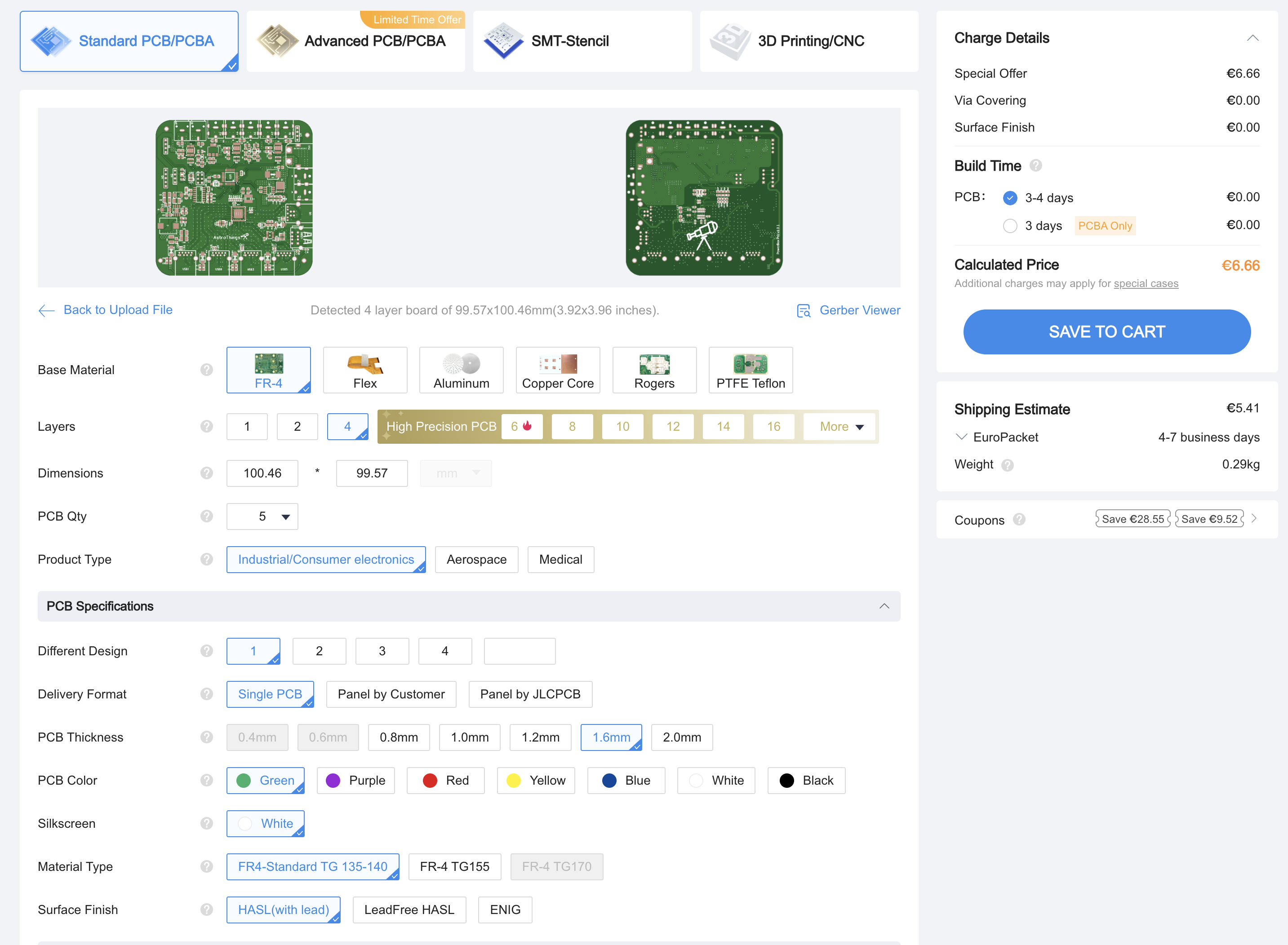
IMPORTANT: Pro Version PCB Order Settings
- Impedance Control → Enable JLC04161H-7628 (no extra cost).
- Copper weight → 1 oz.
- Base material → FR-4.
- Thickness → 1.6mm.
RCA Inputs
- Leave RCA input slots empty during SMT assembly.
- Order separately: L-type RCA jacks.
What’s Next? The Enclosure Build
Now that you know what’s inside, it’s time to put a shell around it. Next post: Building the Enclosure.
Send me an email or use the contact form
Want to buy me beer 🍻? Use this link
See you next time!
~The Bright Knight