If you’re still here, it means that you have everything in hand. In this post, we will go over the installation process.
We’ll cover:
- How to burn the bootloader on the PCB’s microcontroller
- Install the driver (and the external software)
- Activating the Alpaca Dynamic driver
- Troubleshooting
1. Burning the Bootloader on the PCB’s Microcontroller
Whether you received the ATMEGA chip from the factory or ordered and soldered it yourself, it will come without any bootloader – meaning you cannot upload any programs to it. Burning a bootloader enables it to communicate with programming tools and load firmware via standard interfaces like SPI or UART. In other words, you need to have an operating system on your computer before you can install a game on it.
This is a one-time process; once done, all version updates and firmware uploads can be done through the Serial (USB/Bluetooth) connection.
Things We’ll Need:
- Any type of Arduino development board (Uno, Nano, etc.)
- 6 Jumper wires
- A computer with Arduino IDE software (download it from here)
- Nerves
Step 1 - Connecting Everything:
- Disconnect the PCB from any power and USB connection.
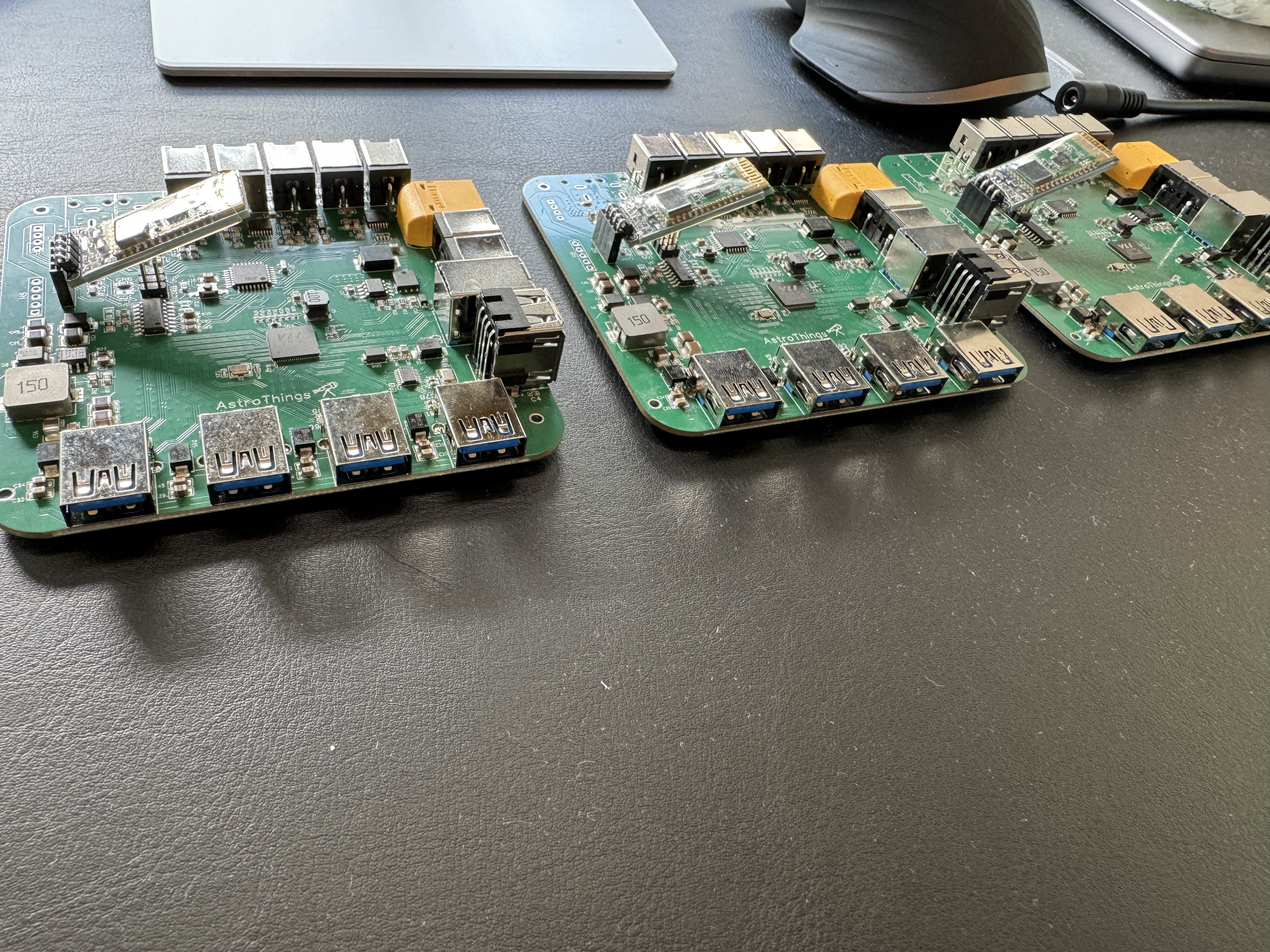
- On the PCB, locate a 6-pin header (2 rows of 3 pins). There will be labels on the PCB for each row – 1 and 2. These headers are our direct connection to the microcontroller.
- Place the PCB in an orientation where the labels 1 and 2 are directly in front of you (not on the side or upside-down).
- Connect the jumper wires in the following order:
- Top row with label 2:
- Top left pin (VCC) – Connect the other end of the jumper wire to the 5V pin on your Arduino board.
- Top middle pin (MOSI) – to pin 11 on your Arduino board.
- Top right pin (GND) – to the GND pin on your Arduino board.
- Bottom row with label 1:
- Bottom left pin (MISO) – to pin 12 on your Arduino board.
- Bottom middle pin (SCLK) – to pin 13 on your Arduino board.
- Bottom right pin (RESET) – to pin 10 on your Arduino board.
- Top row with label 2:
- Connect the Arduino board to its USB cable and plug it into your computer.
Step 2 - Burn the Bootloader:
- Open the Arduino IDE software.
- In the top menu, go to File → Examples → ArduinoISP → ArduinoISP. A new sketch will open up; you can close other opened windows.
- In the top menu, go to Tools → Board → Arduino Boards → select the board connected to your computer (Nano/Uno, etc.).
- In the top menu, go to Tools → Port → select the USB port your Arduino is connected to. If you’re unsure, disconnect the USB cable, check which port disappears, reconnect it, and the correct port will show up.
- In the top menu, go to Tools → Programmer → select “Arduino as ISP.”
- In the top menu, go to Sketch → Upload and wait for it to finish (see troubleshooting below if it’s not working).
- In the top menu, go to Tools → Burn Bootloader and wait for it to finish.
- If it finished successfully, the LED on your PCB should blink repeatedly.
Troubleshooting:
If there are issues with the initial upload:
- Disconnect the jumper wires from the Arduino board.
- Make sure the Arduino board is connected to your computer and that you selected the correct board and port.
- If it’s still not working, go to Tools → Processor → Switch between ATMega328P and ATMega328P (Old Bootloader); one of them should work.
If there are issues with burning the bootloader:
- Make sure all jumper wires are connected properly.
- Make sure the PCB is not connected to anything other than the jumper wires.
Step 3 - Upload the Firmware:
- Disconnect all jumper wires and leave only the Arduino board connected to the computer with a USB cable.
- Open the Arduino IDE and load one of the sketch examples (File → Examples → Basics → Blink) and upload it to your Arduino board – make sure it uploads successfully.
-
In the output screen at the bottom, the third line will show the
avrdudecommand, something like:- Windows:
C:\Users\thebrightknight\AppData\Local\Arduino15\packages\arduino\tools\avrdude\6.3.0-arduino17/bin/avrdude.exe "-CC:\Users\thebrightknight\AppData\Local\Arduino15\packages\arduino\tools\avrdude\6.3.0-arduino17/etc/avrdude.conf" -v -V -patmega328p -carduino "-PCOM12" -b57600 -D "-Uflash:w:C:\Users\thebrightknight\AppData\Local\Temp\arduino\sketches\example\Blink.ino.hex:i" - Mac:
/Users/thebrightknight/Library/Arduino15/packages/arduino/tools/avrdude/6.3.0-arduino17/bin/avrdude "-C/Users/thebrightknight/Library/Arduino15/packages/arduino/tools/avrdude/6.3.0-arduino17/etc/avrdude.conf" -v -V -patmega328p -carduino "-P/dev/cu.debug-console" -b57600 -D "-Uflash:w:/Users/thebrightknight/Desktop/arduino/sketches/example/Blink.ino.hex:i"
- Windows:
- Download the
.hexfile from the GitHub repository. Make sure it fits the version (Essential/Pro). Do not use the files with “_Update” in their names. - Disconnect the Arduino board and connect the PCB to the computer with a USB cable to the same port.
- Open the command line (Windows key + R) on Windows, or a Terminal on Mac/Linux and paste the command.
- Change the last flag in the command to the location where the
.hexfile you downloaded is stored. For example:- From:
-D "-Uflash:w:C:\Users\thebrightknight\AppData\Local\Temp\arduino\sketches\example\Blink.ino.hex:i" - To:
-D "-Uflash:w:C:\Users\thebrightknight\Downloads\PowerBox_Pro_v1.1.9.hex:i" - Make sure to keep the
-Uflash:w:and the:iat the end.
- From:
- Press Enter, and the firmware will upload to the microcontroller. You should see a success message at the end.
That’s It! The Firmware Is Installed!
2. Installing the Driver
- Ensure you’re connected to the internet.
- Go to the GitHub repository, download the installation package “AstroThings Setup v1.1.9” (NOT the ASCOM file) and install it. Make sure to check the box to create a shortcut on your desktop (you can delete it later).
- When prompted to install Node and dependencies, check both boxes and click Finish. This will start another installation process for Node. Follow the prompts to install it. A new terminal window will open to install all dependencies (this may take a few minutes).
Congratulations! The drivers are now installed!
3. Connecting to the PowerBox
- Connect your PowerBox to the computer with a USB cable.
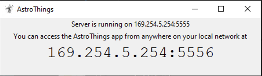
- Click the new shortcut on your desktop. The first time will take a few moments to load. It will open a new window with the Server information. After some time, a new browser window with the Web app should appear. If not, manually open your browser and enter the IP assigned to it (listed in the small window with the server details, e.g.,
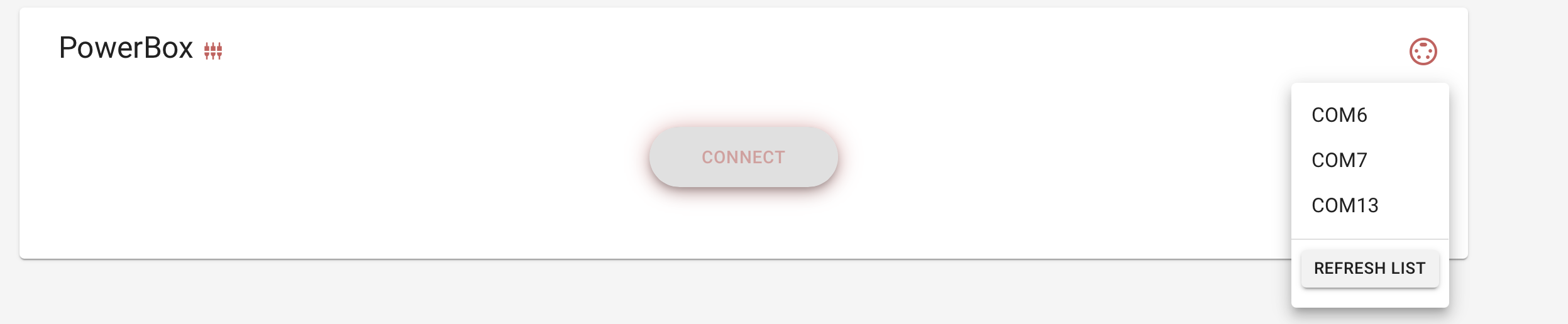
192.168.X.X:5556). - Once the app is loaded, click the Connect button and then click on the refresh icon next to it. Select the COM port and click Connect.
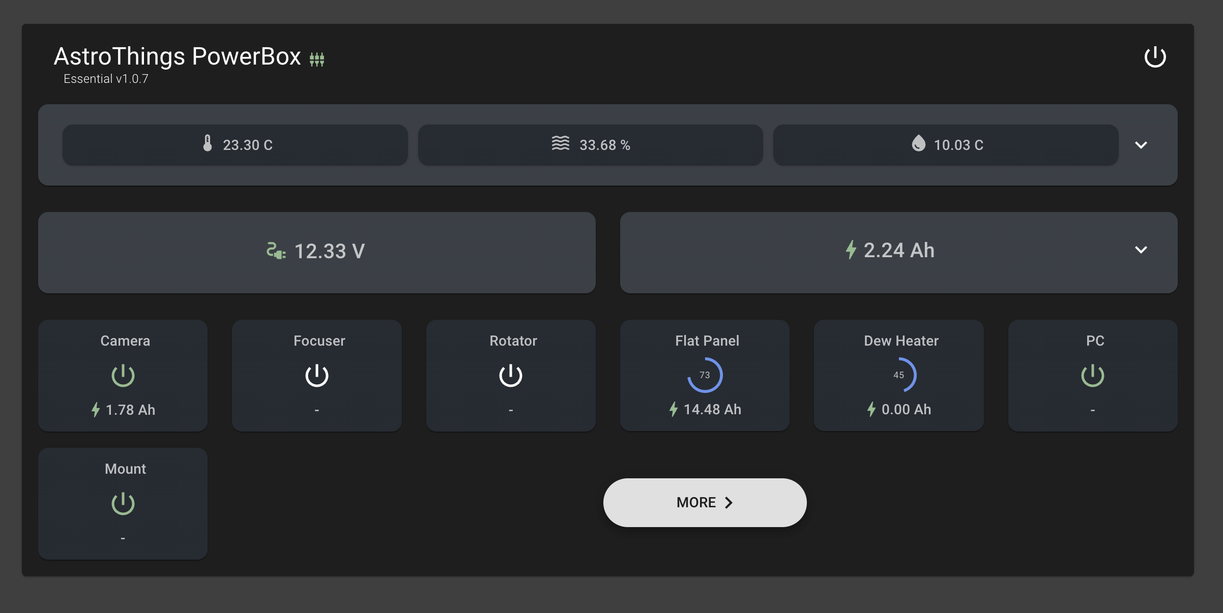
- Once connected successfully, you will see all the ports and their status. Clicking on More will open a detailed view with advanced controls.
You can connect to the Web App from any device (smartphone/tablet/computer) that is connected to your network by simply opening the browser and entering the IP (e.g., 192.168.X.X:5556).
4. Connecting to the PowerBox with N.I.N.A (or any other software)
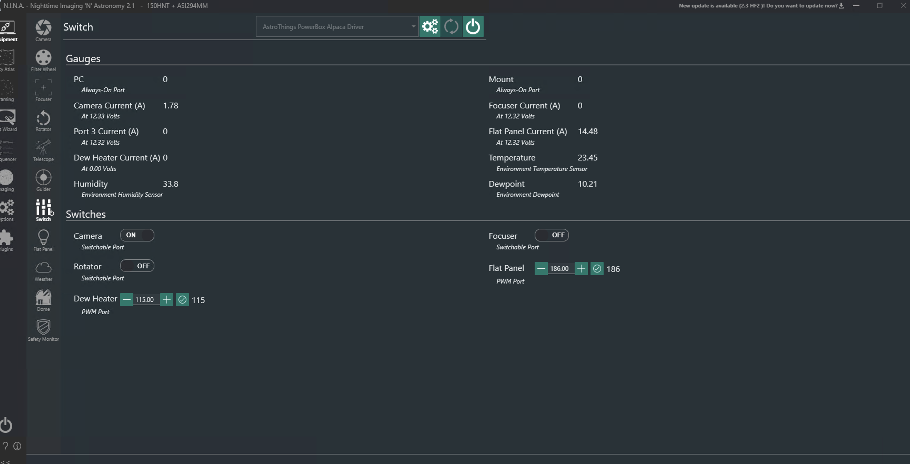
This is a one-time process. After installing and connecting to the Web app, you need to set up the Alpaca Dynamic Driver to access it from N.I.N.A or other software:
- In the Web app, click on the gear icon in the top right corner → Dynamic Driver Setup → Click Setup and wait for it to finish.
- Open N.I.N.A and go to the Switch devices section. The new device should now be available for use and can be connected.
5. Connecting to the PowerBox via Bluetooth (Without USB Cable)
You have the option to add a Bluetooth module to the PCB, which enables you to connect to the PowerBox wirelessly. The module needed is an HC-06 module. You can find it here.
Steps:
- Bend the pins and connect the Bluetooth module to the PCB (check the guide for connection details).
- Once connected, ensure the module has power. Open the Windows Bluetooth settings, add the device, and connect to it.
- You will now have new COM ports to choose from when connecting to the PowerBox. Select the Bluetooth port and click Connect as you would with a USB cable.
Note: When connecting in Windows Bluetooth settings, there will be two types (BLE and regular), but Windows doesn’t always indicate which is which. Just add both. One will request a PIN code—use 1234.
6. Connecting External Temperature and Humidity Sensors
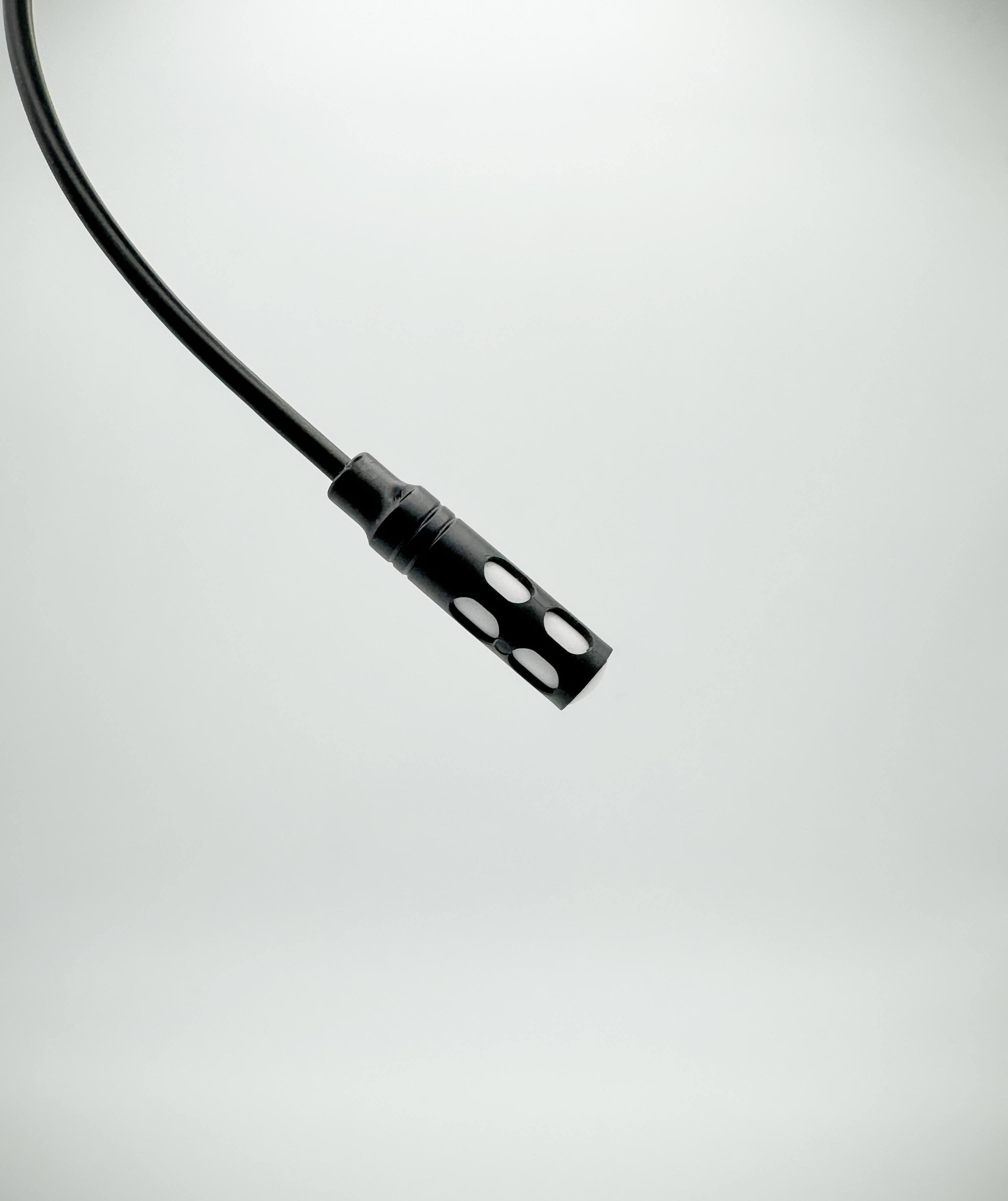
The box has an internal sensor, but if you want more accurate readings, you can connect an external sensor like the SHT30/31 to the 4-pin output port.
Notes:
- Logs can be found at
%appdata%\Local\AstroThings\powerbox.log. - The
config.tomlfile is also located here, where you can change the Web port (not recommended). The COM port updates automatically when selected in N.I.N.A or the UI, so you can leave it. - If there are issues during installation, use the ASCOM Diagnostics tool to check configurations.
- Sometime there issues with the configurations during installation - to confirm everything was set up correctly open ASCOM Diagnostics tool → on the top bar click on Choose device → Choose and connect to device → In the new window Select device type to Switch and click on “Choose” → In the new window select AstroThings PowerBox Alpaca Driver and click on properties , it will take 5-20 seconds to respond and a new window will open up → Make sure that the Communication timeouts fields are set (in this order) to 10, 10 and 120.
- If you couldn’t even find the AstroThings PowerBox Alpaca Driver then the Alpaca dynamic driver is not installed - in the same window click on Alpaca tab and Manage Devices → Make sure that AstroThings PowerBox Alpaca Driver is not listed, if yes select it and click Delete
Now you have a fully working PowerBox that you can connect to from anywhere!
In the next post, we will go over the software features.
Send me an email or use the contact form
Want to buy me beer 🍻? Use this link
~ TheBrightKnight